Oak Ridge National Laboratory and Boeing Bring Stamp Form Die Technology to Aviation— What Is It?
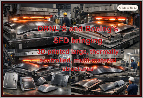
Oak Ridge National Laboratory and Boeing
Bring Stamp Form Die Technology to Aviation—
What Is It?
Oak Ridge National Laboratory has published the attached article about a joint project with Boeing to create a massive Stamp Die Form (SDF) for aerospace inter alia use. It is a metal mold for thermoplastic composite parts (e.g., aircraft doors) aimed at faster, cheaper, lighter composite airframes. In about 1,000 words ORNL describes how the SDF includes within its design—
- Wire‑arc additive manufacturing (WAAM) with a robotic arm (Arc‑1), printing steel layer‑by‑layer.
- Multi‑material: Mild steel for internal stiffness, stainless steel on the working face for durability and corrosion resistance.
- Multi‑material: Mild steel for internal stiffness, stainless steel on the working face for durability and corrosion resistance.
- Rapid tooling turnaround: WAAM can print large molds in weeks instead of months of casting/forging/machining.
- Lower cost for complex tools: Curved cooling channels and complex back‑structures are “free” in additive, but expensive in conventional machining.
- High‑rate production: Better thermal control in the mold means faster heating/cooling cycles → more parts per hour, which is exactly HiCAM’s goal.
From the article on can project that the SDF is an excellent machine for:
- Fuselage and wing skins (thermoplastic or thermoset hybrid processes)
- Doors, hatches, fairings, access panels
- Control surfaces (rudders, elevators, ailerons)
Copilot translates the technical descriptions of the ORNL article concludes :
“You can economically create dedicated tooling for more variants and more localized optimization of structures, instead of being constrained by a few ultra‑expensive legacy tools.”
AI also provides an assessment of the SDF’s applications, capabilities, and more micro uses
“APPLICATIONS:
- Stiffened panels with co‑formed ribs, stringers, and local reinforcements
- Complex curvature parts (wing root fairings, blended wing‑body sections)
- Multi‑functional skins (acoustic, thermal, or lightning‑strike layers integrated into the laminate)”
“CAPABILIIES
- Conformal cooling/heating: You can tune temperature distribution across the mold to match thickness, curvature, and resin flow—critical for high‑quality thermoplastic consolidation.
- Local surface materials: Stainless on high‑wear zones, different alloys where you need different thermal or mechanical behavior.
- Topology‑optimized back‑structures: The mold itself can be lightweight yet stiff, designed via simulation and then printed as‑is.”
“FUTURE APPLICATIONS
- Fan case and nacelle composite tooling (thermoplastic or resin‑infused)
- Acoustic liner panels (perforated face sheets + honeycomb cores)
- Composite brackets, mounts, and fairings around the engine and pylons
- Improve cycle time for forming thermoplastic liners and panels.
- Enable complex perforation patterns and curvature via better thermal control and more precise forming.
- Reduce tooling cost for multiple engine variants or customized nacelle geometries.
- Non‑rotating metallic engine structures (mounts, frames, housings) printed via WAAM and then machined to final tolerance.
- Hybrid metal–composite interfaces where the metal side is WAAM‑printed with tailored stiffness and cooling features.
- WAAM is already being explored for large structural metal parts; combining that with ORNL’s residual‑stress simulation and multi‑material capability makes it more viable for engine‑adjacent hardware.
- Reducing lead time for new or revised molds when designs iterate.
- Enabling more localized design changes (e.g., new door cutouts, window layouts, local reinforcements) without prohibitive tooling cost.
- Supporting distributed manufacturing—large tools can be printed closer to final assembly sites.
- Blended‑wing bodies
- Truss‑braced wings
- High‑aspect‑ratio, ultra‑slender wings
- Future single‑aisle replacements, regional aircraft, and advanced transport concepts, HiCAM’s objective is clear: composite airframes at metal‑like production rates.
- Smart tooling with embedded sensors, active heating/cooling zones, or even vacuum paths.
- Molds that double as testbeds for new resins, layups, and forming cycles.
- Adaptive manufacturing processes (closed‑loop control of temperature, pressure, and cycle time).
- Rapid prototyping of advanced laminates (e.g., toughened thermoplastics, recycled fiber composites) with production‑representative tooling.”
“The ORNL–Boeing SFD project isn’t just a big mold—it’s a proof of concept that large, thermally controlled, multi‑material tooling can be 3D‑printed and simulated into shape, enabling high‑rate, high‑complexity thermoplastic composite manufacturing for aircraft and engine structures today, and unlocking more ambitious, integrated, and optimized designs for tomorrow’s airframes and propulsion systems.”
AVIATION depends on
-
-
-
- the engineering advances,
- manufacturing capacity &competence
-
-
and
-
-
-
- the humans that operate/maintain/regulate flight
-
-
must have keen and current COMPREHENSION of how their individual role impacts SAFETY as innovation infuses the business. Any segment of these three independent functions that is not 100% current with the others may degrade the AVIATON’s #1 mission- the transporting of people and goods.

Partnership Between ORNL, Boeing Advances Manufacturing for Aircraft Parts
3D printing a 2-ton tool boosts thermoplastic composite manufacturing
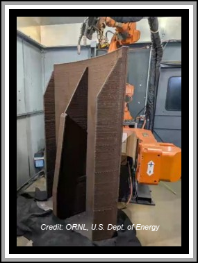
3D-printed metal mold, with temporary support ribs used to maintain shape during fabrication still attached.
by Oak Ridge National Laboratory
Newswise — In a cavernous laboratory, a steady glow traced a path through the air, building up layer after layer of molten steel. Over eight weeks, a MASSIVE STAMP FORM DIE (SFD) MOLD emerged—6 feet tall, 4 feet wide and weighing nearly 2 tons.
 A Stamp Form Die is a punch press used to cut or shape materials. The 3D-printed metal mold was developed through a partnership between the Department of Energy’s Oak Ridge National Laboratory (ORNL) and the Boeing Company to explore state-of-the-art manufacturing methods for SFD tooling in THERMOPLASTIC COMPOSITE[1] PRODUCTION.
The SFD will be used by Boeing to contribute to NASA’s Hi-Rate Composite Aircraft Manufacturing (HiCAM) project.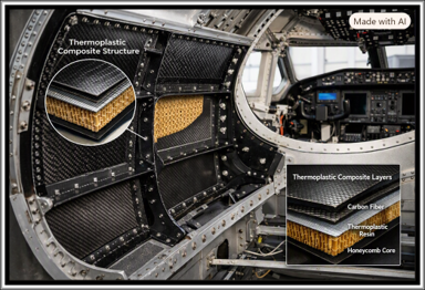
“NASA and its industry partners are working to increase the production rate of composite aircraft to meet the growing demand for air travel and to reduce aircraft weight, which improves fuel efficiency, lowering costs for aircraft operators,” said Richard Young, NASA HiCAM Project Manager. “Doing so is essential to maintaining U.S. competitive advantage in the commercial aircraft industry.”
Boeing utilized a network of American small and large businesses to execute the 3D-printed SFD tool project, applying cutting‑edge technology and engineering expertise to overcome complex technical challenges.
“It is imperative American companies continue to innovate and push technical boundaries to retain our competitive advantage in the global marketplace,” said Boeing Technical Fellow Michael Matlack.
A new way to make a mold
Thermoplastic aircraft doors are made by stamping hot plastic between two SFD metal molds. Think of the molds as slices of bread for a sandwich, with a sheet of hot plastic as the filling.
Normally, these molds are made through traditional metalworking such as machining, casting, forging, and drilling. Researchers at Boeing and DOE’s Manufacturing Demonstration Facility (MDF) at ORNL wanted to see whether it would be faster, less costly, and easier to 3D print a thermally controlled SFD mold instead.
“Boeing wanted to explore the possibility of using wire-arc additive manufacturing (WAAM),” said William Carter, ORNL robotics engineer at the MDF. “They worked with us to evaluate the issues in making the mold.”
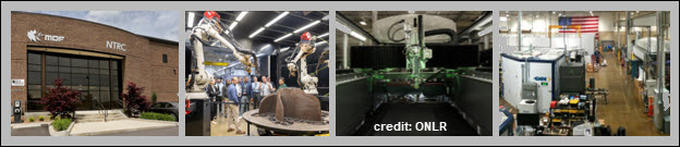
This project relied on ORNL engineering expertise in WAAM processes and residual stress simulation, using ORNL’s Arc-1 system. Arc-1 has a robotic arm and a welding torch to melt wire and build metal parts layer by layer. Unlike most WAAM systems, Arc-1 can print with more than one kind of metal, feeding in multiple wires at the same time. This increases manufacturing versatility, broadens the range of printable geometries, and allows multiple metals to be combined with greater design flexibility for tailored performance.
“Multi-material WAAM allows for the realization of completely new designs, combining fine-tuned mechanical performance with time and cost savings,” said Andrzej Nycz, ORNL senior robotics engineer.
The Boeing SFD mold leverages mild steel in the structural regions for strength and stiffness, while stainless steel is deposited at the mold surface to provide corrosion resistance, dimensional stability, and a durable working interface.
Such molds usually have long, straight holes drilled into them to create channels that will carry heating and cooling fluids. With 3D printing, engineers were able to instead build in curving channels that closely follow the shape of the mold. This helps heat and cool the part more efficiently and improves mold performance.
One major challenge to 3D printing the mold was warping. As the deposited metal cooled, inherent residual stresses caused twisting and dimensional drift. TO MINIMIZE THIS, THE TEAM ADDED TEMPORARY RIBS TO THE BACK OF THE MOLD AND USED COMPUTER SIMULATIONS TO REFINE THE DESIGN AND COMPENSATE FOR THIS WARPING DURING THE PRINTING PROCESS. After 32 simulation iterations, they produced a mold that was within a few millimeters of the intended shape.
Once the mold was successfully printed, it was sent to Baker Industries in Michigan to be annealed to remove internal stress. The support ribs were then cut away. Baker Industries completed all remaining fabrication operations to finish the SFD to achieve all Boeing requirements.
A mold that could help shape the future
The wire-arc technology used to manufacture the tool was developed as a collaboration between ORNL and Lincoln Electric under a Cooperative Research and Development Agreement (Baker Industries is a subsidiary of Lincoln Electric). “Baker Industries values its strong partnerships with ORNL and Boeing,” said Evan Bartkiewicz, Baker Industries senior project manager.
The project highlights how leveraging engineering and scientific expertise of collaboration partners can achieve the objective in a timely manner.
While not all parts of the final tool were 3D printed, the technology developed within this project can be replicated for similar tool types.
“We used this as a test case,” said Ahmed Arabi Hassen, ORNL’s group leader for Composites Innovation. “Its success means the technology could be used to make large thermoplastic structures for other sectors of U.S. industry, such as energy and automotive.”
By proving that large, COMPLEX TOOLS CAN BE 3D PRINTED FASTER AND MORE EFFICIENTLY THAN WITH TRADITIONAL METHODS, ORNL and its partners are strengthening the U.S. industrial base while opening new doors to innovation.
UT-Battelle manages ORNL for DOE’s Office of Science, the single largest supporter of basic research in the physical sciences in the United States. DOE’s Office of Science is working to address some of the most pressing challenges of our time. For more information, visit energy.gov/science.
[1] Thermoplastic composites (TPCs) are defined as materials featuring a thermoplastic matrix that can be softened and remolded upon heating without degrading, allowing them to harden into a final shape upon cooling. They are increasingly valued for their lightweight properties and ability to replace metals in various industries, contributing to the production of more fuel-efficient vehicles and structures. https://www.sciencedirect.com/topics/engineering/thermoplastic-composite.